This is a guide to setting up and using the RN-134 WiFi module with MegaSquirt. Assuming you have the basic RN-134 that comes as a bare module you will need to do two things to get it working with your MegaSquirt.
The first task is to create a serial cable to provide the hardware interface to your MegaSquirt ECU. The RN-134 has a 10 way “header” connector that supplies all the connections you need to the serial DB-9 connector. One word of warning though if you’ve got the manufacturers technical manual, the pinouts as described in the manual are actually wrong. To provide the module end of the cable I bought a 10 way motherboard serial extender cable, available from most PC component suppliers. I used this one.
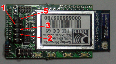
To simplify the process (hopefully) the image below shows an image of the header connector and the pin numbers on the DB9 male connector that they should be connected to. This pin out should enable the board to be powered through the serial port regardless of which MS board version you are connecting to. The pin that is to be connected to pin 1 of the DB9 connector is the power supply. As mentioned earlier some versions of the module’s manual incorrectly show this as the RTS pin.
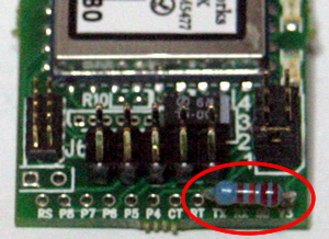
If you are using the module with an MS2 you will also need to add a pull up resistor to the board to stop the MS2 CPU going into a configuration mode when you power the MS2 up with the WiFi module connected. This modification isn’t needed for MS1 versions although it might be worth doing anyway as it does no harm as it stops the TX line going high during initialisation. Connect a 22K Ohm resistor between the edge connector holes marked V3 and TX pins 1 and 4. A picture of a modified board is shown below with the resistor circled in red…
You should now have a fully operational module, make sure there is a jumper connected at position 1 of the options select pins. This is pictured above, immediately above and towards the right of the resistor. That will ensure the module powers up in ad-hoc mode. When you connect the module to your MegaSquirt and power it up you should see the blue LED come on solid, the red, yellow and green LEDs will be flashing. If you go to the settings panel on your iPhone/iPad/iPod and select WiFi you should see a network with a name similar to “Wifly-GSX-xx” which you can select to join, at this point the LEDs on the module should change with the yellow LED turning off. The xx is replaced by the last two digits of your module’s MAC address, you don’t need to worry about the MAC address if you don’t know what it means, it just means that if there is more than one module in the area you can make sure you are connected to the right one !
If you want to test the link there is an IOS utility available on the app store as a free download called “WiSnap+”. Although this is a utility designed to be used with the WiSnap products it will work with the RN-134 as the WiSnap uses the same module. As well as testing the configuration you can also use the utility to configure the module so it plays nicely with MS, mainly by stopping the module sending any messages out on it’s uart (serial) port.
The default address details for the RN-134 are as follows…
Host Address: 169.254.1.1
Port Number: 2000
MobiSquirt should have the ability to configure the module for you automatically but if you’d prefer to configure it yourself the following commands are required (the command reference is available from Roving Networks’ web site).
$$$ (or %%% if the WiSnap utility has changed the default) – enter command mode
set comm close 0 (numerical zero) – Stop the module sending status messages when a network connection is closed
set comm open 0 (numerical zero) – Stop the module sending status messages when a network connection is opened
set uart mode 0x10 – clears all the waiting data if a connection is closed
set uart baud 9600 (for MS2 and later use 115200 instead of 9600)
set sys printlvl 0 (numerical zero) – Stop miscellaneous status messages being sent down the serial port
save – save your changes
exit – leave command mode
You’ll need to power cycle the module to get the settings to take effect.
As a reference, this is the result of the “get everything” command on a working module…
Beacon=100
Probe=9
OPEN=
CLOSE=
REMOTE=*HELLO*
FlushSize=75
MatchChar=0
FlushTimer=10
IdleTimer=0
CmdChar=%
IF=UP
DHCP=ON
IP=169.254.1.1:2000
NM=255.255.0.0
GW=0.0.0.0
HOST=0.0.0.0:2000
PROTO=TCP,
MTU=1460
FLAGS=0x7
BACKUP=0.0.0.0
DNS=161.72.0.0
Name=server1
Backup=backup2
FTP=208.109.78.34:21
File=wifly-GSX.img
User=roving
Pass=Pass123
SSID=roving1
Chan=0
ExtAnt=0
Join=1
Auth=OPEN
Mask=0x1fff
Rate=12, 24 Mb
Passphrase=rubygirl
SleepTmr=0
WakeTmr=0
Trigger=0x1
Autoconn=0
IoFunc=0x0
IoMask=0x20f0
PrintLvl=0x0
TimeEna=0
TIMEADR=129.6.15.28:123
Zone=7
Baudrate=9600
Flow=0x0
Mode=0x10
JoinTmr=1000
Replace=0x24
DeviceId=WiFly-GSX
Password=
BCAST=255.255.255.255:55555
Interval=0x7


