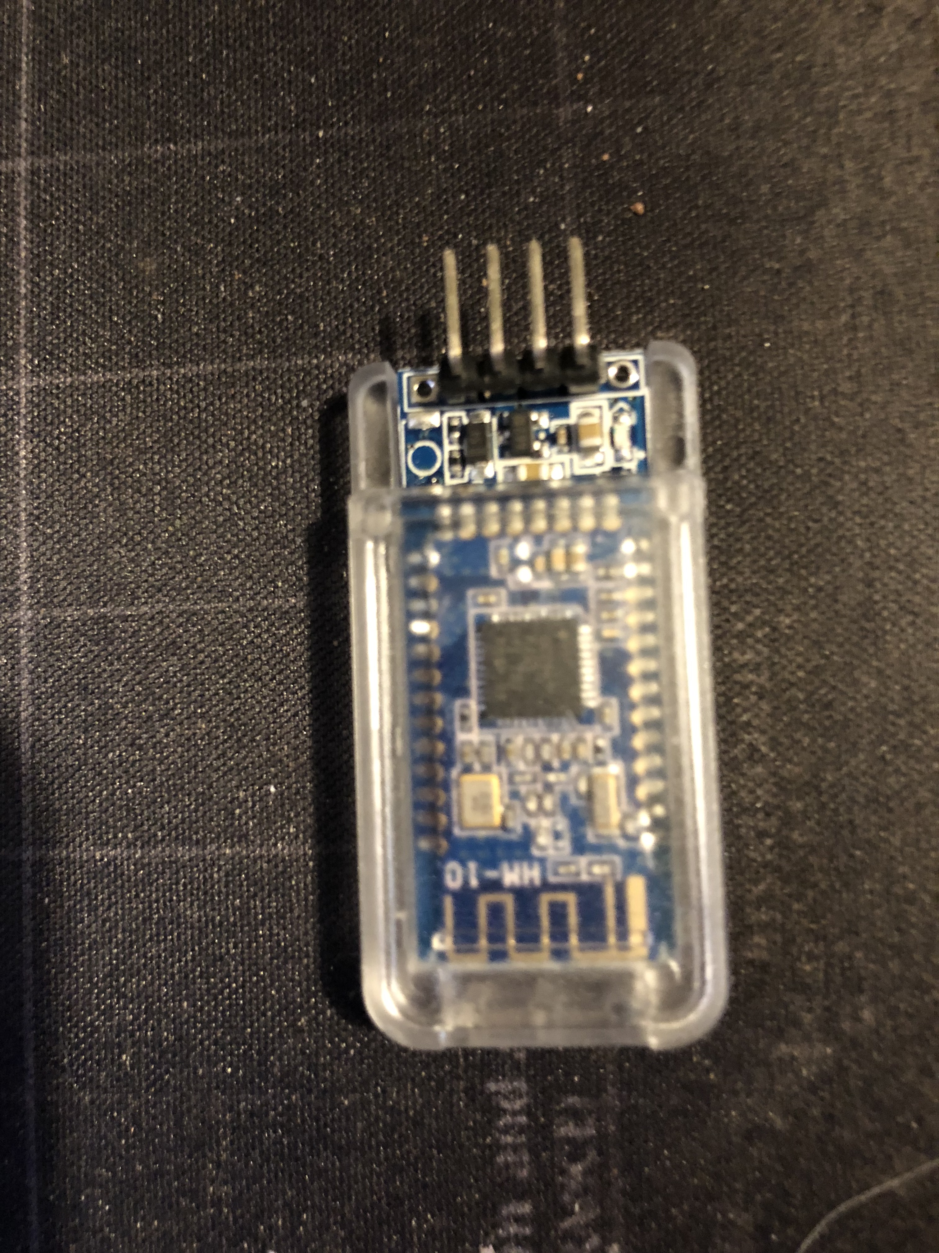
I’m using an HM-10 module, pictured here, but the HC-08 is pretty much identical to look at. This particular one comes in a clear plastic case but many don’t and it’s not necessary. We’re only interested in 4 connecting pins and most modules only come with those 4 with header pins installed.
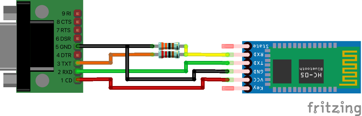
Connecting the two modules is easy enough, they both have 4 pins and you need to connect VCC to VCC, GND to GND, TX on the serial module to RX on the BLE module and RX on the serial module to TX on the BLE module. In theory you should use a dropper circuit between the TX of the DB9 module and the RX of the BLE module. In practice, so far at least, they’ve coped quite happily being connected directly. On my serial module the power pins are marked as VCC and GND but the tx/rx are replaced with arrows with an arrow pointing towards the pins for TX and away from the pins for RX.
To add a dropper circuit between the RS232 module TX and the BT module RX, use a 3K Ohm and 2K Ohm resistor (3k3 or 2k2 is fine). A diagram of the necessary connections is shown below… 2K resistor is the lower one of the two in the image.
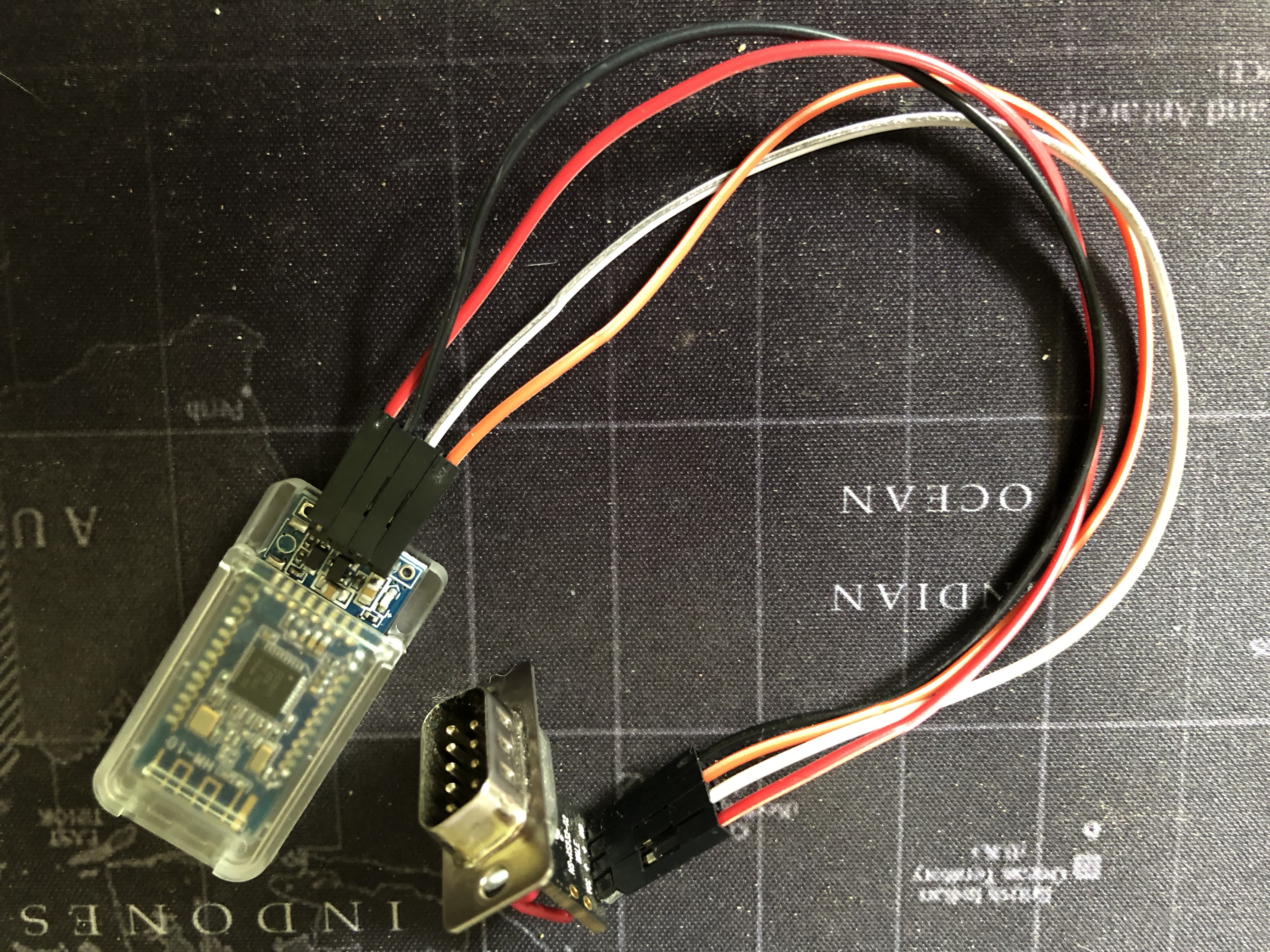
To make the connections you can simply use small female to female patch cables (these may have come with one of your modules) or solder the wires. The images show my prototype using patch cables which I have hundreds of ! These can be bought from Amazon/eBay etc… often advertised as Arduino patch or interconnecting cables.
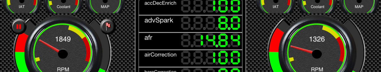
Plug the “finished” connector into your ECU and switch the ECU on. You should see a flashing red light appear on the Bluetooth module to indicate that it is powered up. Once you connect your iOS device via Bluetooth that red light will change from flashing to solid.
To configure the HM-10 or HC-08 module, changing baud rates, setting a PIN, changing the device name etc… more information here.