
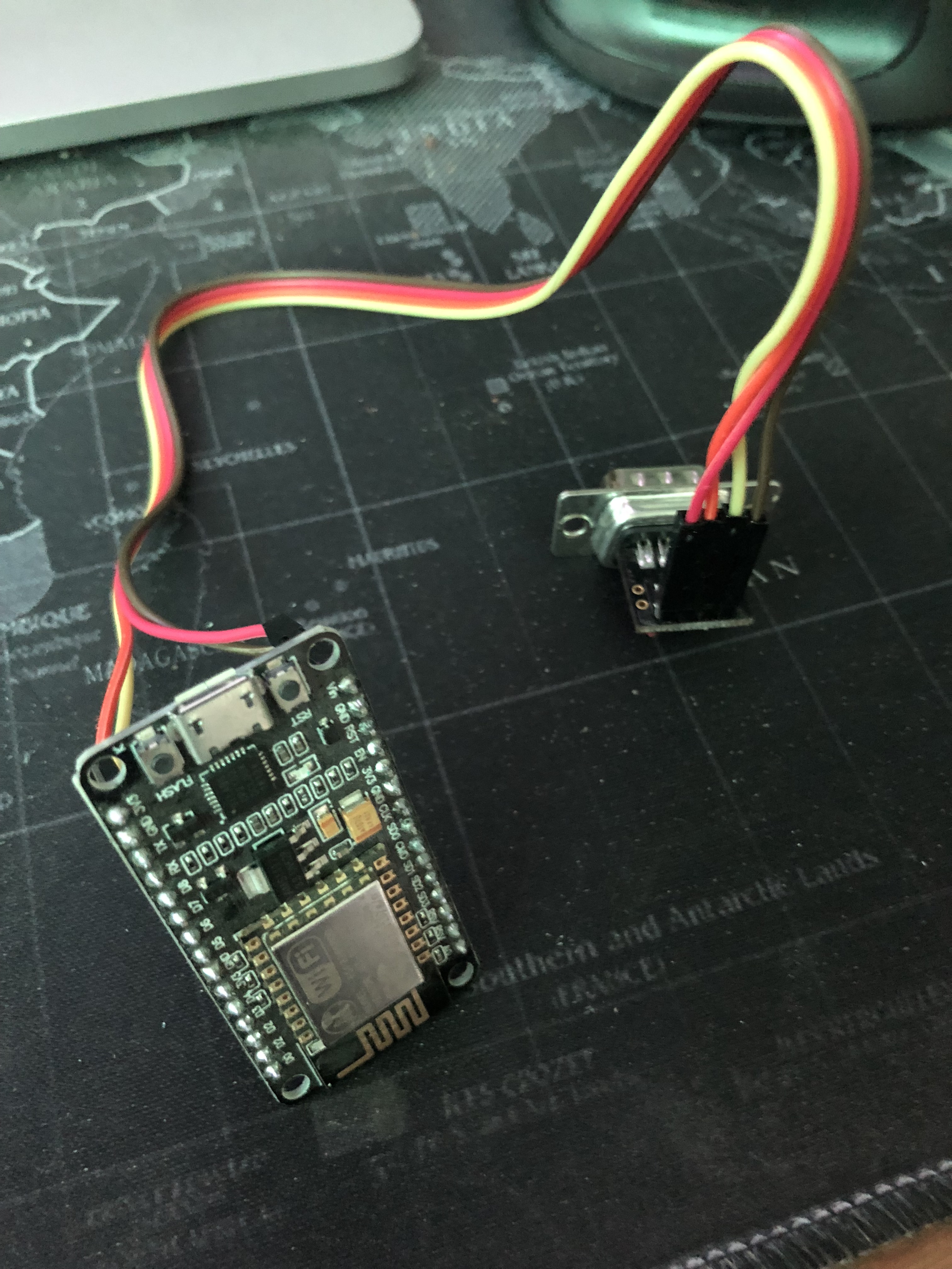
To connect the prepared RS232 connector to your prepared NodeMCU module you need 4 jumper wires.
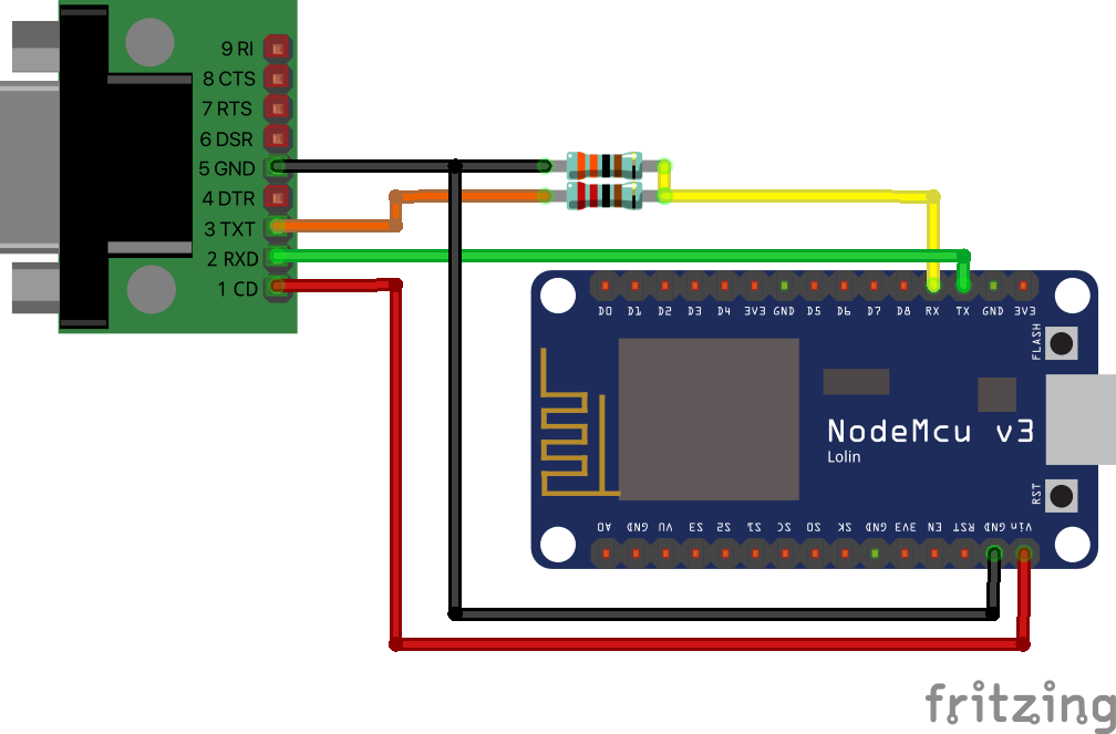
Connect the VCC pin on your RS232 module to the Vin pin on the NodeMCU NOT the 3v3 pin !
Connect the GND pin on the RS232 module to the GND pin on the NodeMCU (any GND pin will do).
Connect the TX or “out” pin on the RS232 module to RX on the NodeMCU. I added a resistor bridge into this connection to drop the voltage from 5v to 3v although the NodeMCU may work with 5v direct it’s probably not a good idea in the long term and adding a couple of resistors to drop the voltage to the RX pin from 5v to roughly 3v is not going to do any harm. I use a 2K Ohm and a 3K Ohm resistor. The 2K Ohm is shown as the bottom of the two resistors in the diagram below. 3K3 and 2K2 will also do the job if they’re easier to source.
Connect the RX or “in” pin on the RS232 module to TX on the NodeMCU.
If you connect the RS232 to your ECU and power it on you should see the LED on the NodeMCU light for a second or two as it boots. After that you should be able to connect to it’s WiFi network.
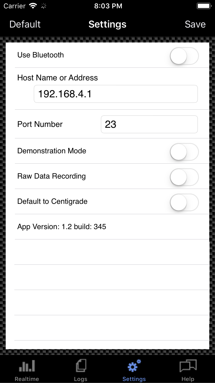 In MobiSquirt, in settings, set the IP address to 192.168.4.1 and set the port number to 23.
I may alter the “default” settings to reflect that in future releases of the app.